A couple of weeks ago, I did a basic breadboard LED project using a mySTEM connected to a myDAQ. We created a simple circuit. This week, we will create a light detector using the mySTEM Project Board for the NI myDAQ and a couple of sensors/circuits. You’ll have a laser emitter that you’ll use to hit a photoresistor, which will send data to LabVIEW. From there, it will then output a signal that triggers a red LED if the light hitting the photoresistor is large enough to surpass a threshold in the LabVIEW graphical programming environment.
Get started by watching this video tutorial. Project instructions appear below!
What You’ll Need – Materials List
Here is what you need to get started on this project:
- mySTEM Project Board
- NI myDAQ Data Acquisition Device
- NI LabVIEW software
- Photoresistor (I’m using a SunFounder Photoresistor Module)
- Laser Emitter (I’m using a SunFounder Laser Emitter Module)
- Dual-Color LED (I’m using a SunFounder Dual-Color LED)
- 2x 3-pin anti-reverse cables
- 1x 2-pin anti-reverse cable
- 2x pin-pin anti-reverse cables
- 12v DV power supply (this should be included with the mySTEM project board)
- USB Type B connector (this is for connecting the MyDAQ to your computer)
Setting up mySTEM to Detect Light Levels
NOTE: I will use colored shapes in my pictures to try and show which pins go where. The color of the shape corresponds to the color of the cable in my picture.
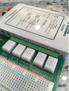
- First, plug your myDAQ into your computer using your USB cable and connect your mySTEM board to the myDAQ terminal.

Get Connected
- Connect your 12v DC power supply to the mySTEM board and switch the power switch on by pushing it towards the board, not away from it. (NOTE: If you are not comfortable with breadboarding, then you should NOT leave this on while you are plugging cables in.)
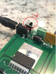
Turn On mySTEM Project Board Switch
- Connect power to the breadboard. To do this, plug a pin-pin cable into the 5V input on the board and connect it to the + column on the breadboard. You also need to supply a ground to the breadboard. To do this, connect another pin-pin cable from the ground input into the – column of the breadboard.
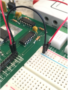

Connect Power to Breadboard
- Connect the laser emitter to the breadboard. Plug your 2-pin anti-reverse cable into the pins of the laser emitter. Plug the VCC pin into the positive column of the breadboard. Plug the SIG pin of the emitter into the ground column of the breadboard.
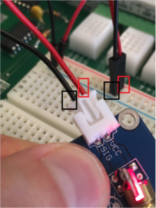

Connect the Laser Emitter to the Breadboard
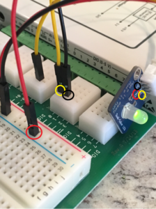
- Wire up the photoresistor. Plug your 3-pin cable into the photoresistor. Plug the VCC pin into the positive column and the GND pin into the ground column. We need to be able to send analog data from the photoresistor to our LabVIEW software. To do this, we will need to connect our SIG pin to the AI +1 input. This input will convert our digital signal to an analog signal so we can measure the amount of light hitting the photoresistor.

Wire Up the Photoresistor
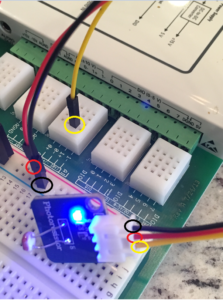
- Wire up the dual-color LED. Plug your 3-pin cable into the dual-color LED. Connect the GND pin to the ground column. Plug the R pin into DIO 0 and the G pin into DIO 1. The DIO ports allow us to get a signal from LabVIEW and send it to our LED module. With this setup, we can control whether the LED is Red or Green by sending a signal to either DIO 0 or DIO 1.(NOTE: My red cable is connected to GND. Yellow connected to R and Black connected to G)

Wire up the Dual-Color LED
- Check your work. Your setup should look something like this.
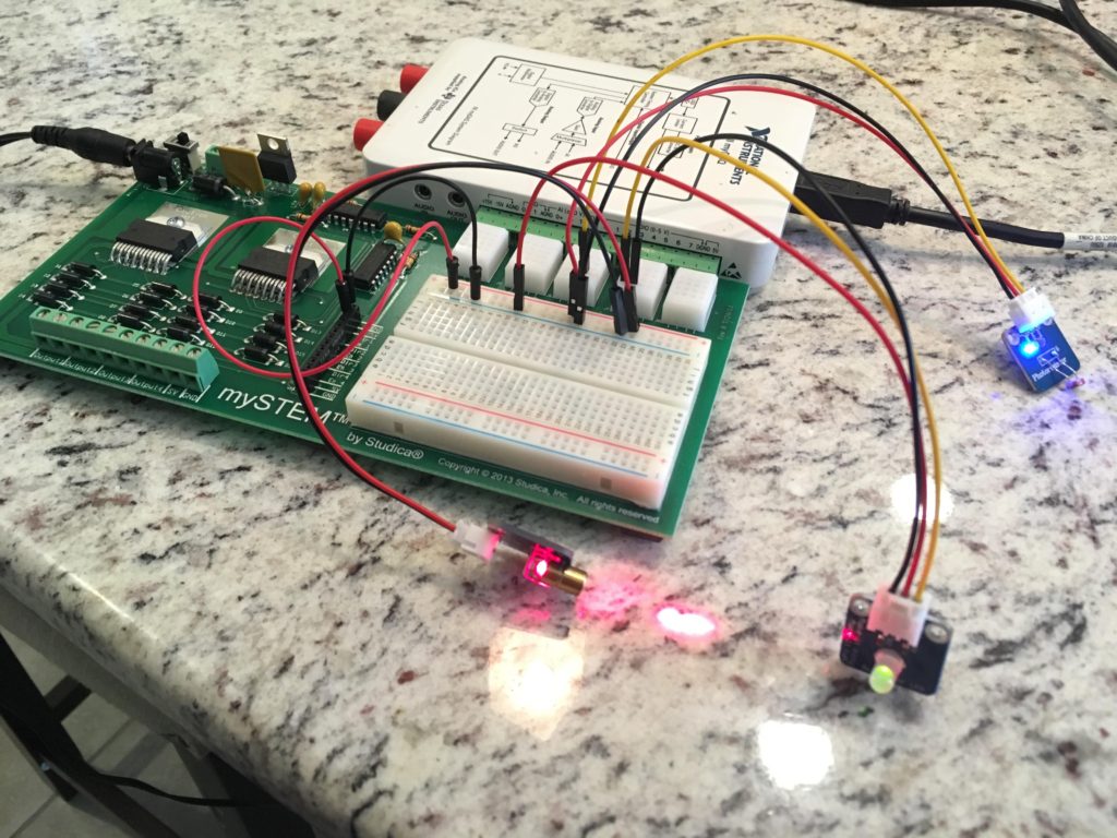

Finished Project
(Your LED light might not turn on right now. This is OK.)
Using LabVIEW to Finish the Job
Make sure your MyDAQ is connected via USB to your computer. Make sure your mySTEM board has power supplied and is turned on. I will be using LabVIEW 2015 for this. I will assume you have a basic understanding of how to use LabVIEW.
- Open LabVIEW and create a new, blank VI.
- On your front panel, add a numeric indicator.
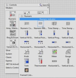

LabVIEW Add Numeric Indicator
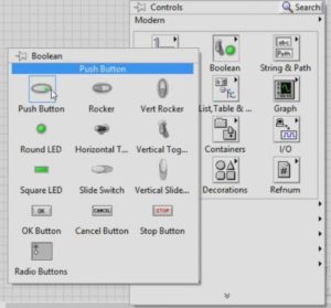
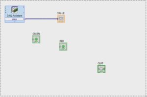
- Add 2 Round LED Boolean objects to your front panel. Name one of them “GREEN” and the other “RED”. These LED’s will light up depending on the value our photoresistor sends through the myDAQ.
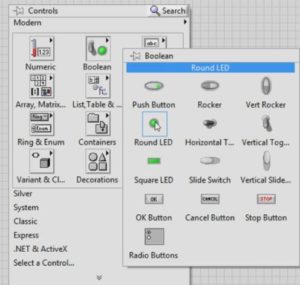

LabVIEW: Add 2 Round LED Boolean objects to your front panel.
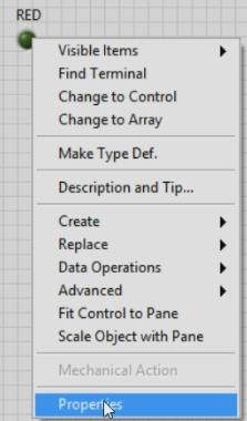
- Right-click on the RED LED object on your front panel and choose “Properties”.

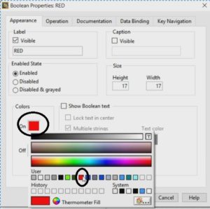
On the properties window, click the “ON” color and select a Red color.

- Add a Boolean push button to the front panel. This will be used as an exit command for our program.

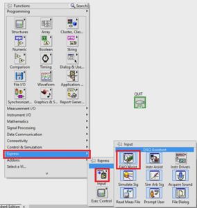
- Open the block diagram (Ctrl+e). Right-click in an empty space and add a DAQ Assistant Input.

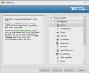
- On the window that comes up, choose “Acquire Signals” → Analog Input → Voltage → Next.

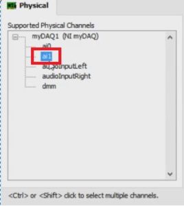
- Choose the ai1 option on the list on the next windowClick “Finish”. On the next window that opens, click “OK”.

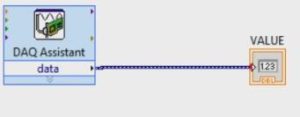
- Connect the DAQ Assistant to the Numeric Indicator block.

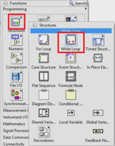
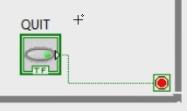
- Add a while loop around all your blocks and wire the QUIT button to the exit condition.

Drag and drop the loop around all your blocks.

Now wire the QUIT button to the exit condition.

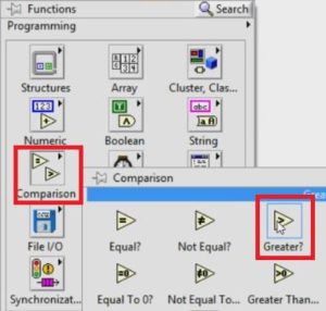
- Add a Greater than Comparison operator to the block diagram.

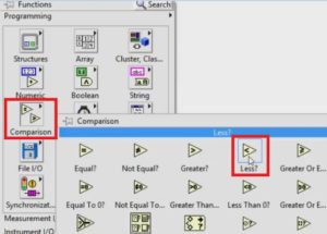
- Add a Less than comparison operator.

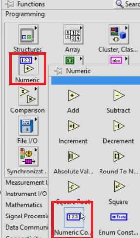
- Add a numeric constant and give it a value of 2 (NOTE: You will probably need to adjust this value depending on the analog value of the ambient light in your room that the photoresistor detects. You can get a decent idea of this value by watching the numeric indicator on the front panel when you run the program).

- Add a new output DAQ Assistant.
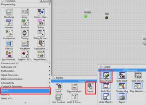
- On the window that comes up, choose Generate Signal → Digital Output → Line Output.
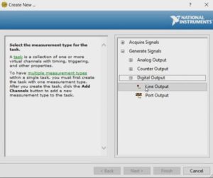

- Choose Line 0. Line 0 will send data to our Red pin on our LED. Click “Finish”. Click “OK” on the next window that opens.
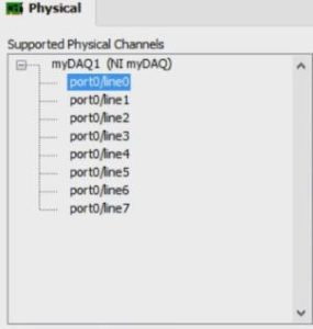

- Repeat step 16 except instead of choosing line0 on the physical channel, choose line1. Line 1 will send data to our Green pin on the LED.
- Wire everything together. Use this screenshot as a guideline:
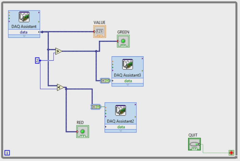

DAQ Assistant2 is sending to our Red LED
DAQ Assistant1 is sending to our Green LED - Once you have this all working, you should be able to run your program and see the LED change color depending on the light intensity that hits the photoresistor.


Understanding the Logic
This is a rather simple setup, but let’s run through what’s happening in the LabVIEW program.
- Our DAQ Assistant is providing output to the rest of our program. We setup the DAQ Assistant so that it is getting analog data from AI 0 from our mySTEM board. As the photoresistor is exposed to light, this value changes depending on the intensity of light.
- The analog data is sent directly to our numeric indicator so that we can see the numerical value of the light intensity that our photoresistor is receiving.
- The analog data is also sent to a Greater Than conditional operator, which is compared against a constant numerical value of 2 (yours might be a different number).
- The analog data is also sent to a Less Than conditional operator, which is compared against a constant numerical value of 2 (again, yours might be different).
- If the intensity of light exceeds a value of 2, then LabVIEW will turn on the Green LED indicator in the LabVIEW program. It also sends a signal to DAQ Assistant3, which outputs a signal through DIO 1 on the mySTEM, which is what our G pin from our Dual-Color LED is connected to. This will then tell the Dual-Color LED to turn Green.
- If the intensity of light is less than a value of 2, then LabVIEW will turn on the Red LED Indicator in the LabVIEW program. It will also send a signal to DAQ Assistant2, which will output a signal to DIO 0, which will tell our Dual-Color LED to turn Red.
The overall result is that the Dual-Color LED should stay Green whenever concentrated light (like the laser) is NOT hitting the photoresistor. When concentrated light hits the photoresistor, then we should see our Dual-Color LED turn Red.
Conclusion
This project should illustrate the versatility of the mySTEM project board. The ability to connect the board to LabVIEW opens up a world of possibilities. What I like about this project is the simplicity. It’s not very hard to setup and it helps familiarize you with using sensors and sending/receiving data through some external program. You can see how LabVIEW allows us to utilize software to send signals to physical objects. This is incredibly useful functionality and it is a very common workflow for modern electrical systems. As more and more systems become intertwined with CPU’s, it’s important to know how to utilize software to manipulate hardware like this. Granted, this is a primitive example, but the foundation comes across well.
Blogger: Mark Philipp, Application Engineer at Studica
Share this Post