
We recently posted a blog about embedded programming using the Raspberry Pi. In an effort to provide further information about accessing Raspberry Pi hardware in an embedded environment, this post will dive into using Raspberry Pi’s 1 MHz timer, also known as the system timer. In this post, we will be extending our last project and modifying our Delay function so that it uses the hardware timer instead of CPU cycles to cause a delay. We want to do this because hardware system timers will give us more accurate timing than our previous implementation, which relied on the speed of our CPU core to perform computations for a desired length of time.
How does the Raspberry Pi Timer Work?
Raspberry Pi has both a system timer and an ARM Timer that is based on an ARM AP804. The system timer is part of the GPU and the ARM Timer is part of the ARM CPU. Interestingly, the ARM timer is derived from the system clock. Since the system clock can have a variable clock rate (low power mode, for instance), the ARM timer can be unreliable. We would have to force the system clock to be a constant 250 MHz to get accurate readings from the ARM timer. In an embedded environment, this isn’t necessarily an issue since the system clock should be running at 250 MHz by default. However, for absolute certainty, we will want to use the GPU system timer to ensure accurate timing.
Why use Raspberry Pi’s Hardware Timer?

 In my previous post, I implemented a delay by calculating the number of cycles per loop and figuring out how many loops to execute based on the core clock speed of the processor. This resulted in a somewhat accurate delay. However, there are a few limitations to this approach.
- The most obvious limitation is that the timing did not seem consistent nor entirely accurate. My timing appeared to be plus or minus a few milliseconds.
- Another limitation is that the number of cycles our CPU can cycle per second is tied to the clock speed of the processor. If we wanted to raise or lower our clock speed for any reason, then we would have to update the clock speed in our delay calculation. This is not ideal from a coding perspective. It’s preferable to have code that can be dynamic.
- Lastly, the only way I could get accurate timing using the CPU cycles implementation was by enabling L1 cache and branch prediction. While both features are great and help speed up our processing, we must remember we are working in an embedded environment.
More on Embedded Systems
Embedded systems are usually designed to solve very specific problems. They are intended to use a bare minimum amount of hardware and functionality to save on power, cost, and running time. If we can leave branch prediction and L1 cache disabled to solve our problem, then that is preferable.
The hardware timer allows us to circumvent these issues. The hardware system timer on the Raspberry Pi is a dedicated timer that runs independently from the processor. This solves our problem of having an adjustable clock rate. It also solves the issue of needing L1 cache and branch prediction to accurately calculate CPU cycles. Additionally, the hardware timer gives us incredibly accurate timing. Lastly, using the hardware timer will simplify our code, which is always beneficial.
What You’ll Need
To complete this project, you’ll need the following components:
All components (with the exception of a computer, a flat assembler, and GitHub files) are included in the Raspberry Pi 3 Starter Kit.
- 1 – Raspberry Pi (Model 2 or 3 for this tutorial)
- 1 – GPIO to Breadboard interface
- 1 – GPIO ribbon cable
- 1 – 5v Power Supply to power Raspberry Pi
- 1 – Breadboard
- 4 – Male-Male cables (pin-pin)
- 2 – LED’s
- 2 – 330-ohm resistors
- A separate computer that you can write the program on. It must be running Windows or Linux/Unix.
- ARM Flat Assembler Compiler. You can download it here. You need this to write the program. Install it on your separate Linux or Windows computer.
- Embedded Programming Files from the Studica Github. Unzip the archive so that you have access to the files.
Procedure
First, if you have not done so, read and follow along with our first embedded programming post; “Intro to Programming Embedded Systems with Raspberry Pi”. That post will help introduce you to the concepts used in embedded systems (bare metal). That blog also breaks down all the GPIO code, which I will not be covering in this post.
NOTE: Anytime you are going to remove the SD card from the Pi, make sure the RaspberryPi is turned OFF by unplugging the power to the Pi. This will help avoid data corruption and other issues.
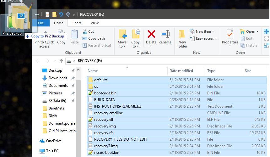
- Just like in our first post, we need to strip the OS off the Pi. Unplug the power from your Pi. Once the power is unplugged, remove the micro SD card. Plug the micro SD card into a micro SD card reader and plug it into your computer where FASMARM is installed.
- Plug the micro SD card into your computer and cut/paste the files into a backup folder on your computer. Basically, backup the current contents of the micro SD card onto your computer. Your Raspberry Pi SD card should be empty after doing this. If you ever want to run Raspbian on your Pi again, you will need to copy these files back onto the SD card.
 Grab the Embedded Timer files from here. Extract the files onto your computer and copy the extracted files onto the SD card of the Raspberry Pi. Your SD card will have this data in it once you’ve successfully done this step:
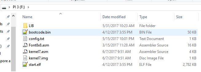
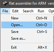
 Go to your FASMARM folder that you downloaded from the link above. Open the FASMWARM.exe file.
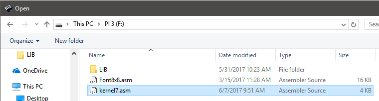
 Once FASMARM opens, click File → Browse to your Micro SD card and open the “kernel7.asm” file.
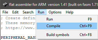
- Once it’s open, you will see the complete code for the project. Go to the Run → Compile option to compile the code out to a .img file. You must do this every time you update the code and want to run the updated code on the Pi.
After doing this, you will see a kernel7.img file on your SD card.
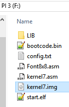
This is the file that our Pi will run when it powers up, which will execute our program.
- Remove the micro SD card from your computer and plug it into your Pi.
- Make sure your Pi has a ribbon cable attached from the GPIO pins to the T-board on your breadboard.
- Plug the Pi power supply into the Pi and you should see your two LED’s take turns going on and off.
If you want to modify your code, repeat steps 5-9 and observe the changes you make. Remember, every time you want to remove the SD card, make sure the Pi is turned OFF.
Breaking Down the Code
If you are new to ARM assembly, take some time and read over the instruction set. There is also a great ARM Assembly reference on ARM’s website.
For the code breakdown, I will only be looking at the Timer function. If you are curious about the rest of the code, refer to the first blog post.
Defining Timer Memory Addresses
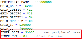
First, we want to define our memory addresses as TIMER_BASE and TIMER_CNT. We are assigning the memory addresses of the hardware system timer to these variables so that it is easier to read and write our code. Note that this is not a necessary step. We mostly do this because memory addresses are not very readable to most people. It is also easier to write code with meaningful names than it is to write code with a bunch of hexadecimal addresses.
How do we know what the addresses are for the timer? To answer that, we must refer to the BCM 2835 manual. The system timer section can be found on page 172. It clearly states, “The Physical (hardware) base address for the system timers is 0x7E003000.” The 0x7E000000 is the base peripheral address of the GPU. We are using 0x3F000000, which is the base peripheral address for the ARM CPU. You’ll notice that their entire address is 0x7E003000. This means that the Timer’s base address must be at memory address 0x3000 since the Pi’s peripheral address is already filled in at 0x7E.
The TIMER_CNT address is at 0x4. We know this from the ST Address Map in the documentation. The memory offset at 0x4 is the lower 32-bits of the counter. We can poke this address to grab microseconds from the timer.
Timer function
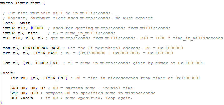
First, we create a macro called “Timer”, which accepts a parameter named “time”. In FASMARM, the macro keyword creates something much like a function in C, C++, and many other high-level languages. Functionally, it’s not much different than writing the following:
void Timer (int time) {}
The macro line allows us to call Timer anywhere else in our code. For instance, if we call “Timer 500”. That line calls the Timer function and passes the value of 500 to it. We can then execute some code in the Timer function. Once the Timer function finishes, execution returns to the line after where “Timer 500” was called.
local .wait specifies a local loop called “.wait”. We will use this loop to count down the time until our delay has been reached.
imm32 r13, #1000 specifies register 13 as a 32-bit register and passes the value of 1000 into it. After this line, R13 now holds the value 1000.
imm32 r5, time specifies register 5 as a 32-bit register and moves the value of time into it. If we call “Timer 500”, then time = 500, which means R5 = 500.
mul r10, r13, r5 is equivalent to r10 = r13 * r5. Remember, R13 is 1000. R5 is set to the time value. If we called “Timer 500”, then this would be r10 = 1000 * 500. This line is both executing a unit conversion and establishing the amount of time we want to delay for. The System timer gives time in microseconds. To get milliseconds from microseconds, we must multiply microseconds by 1000. This is because 1000 microseconds equal 1 millisecond. We could create a delay using seconds by multiplying time by 1000000. However, it’s more common to use milliseconds for delays. After this line executes, R10 will hold the amount of time we want to delay for in milliseconds.
mov r6, PERIPHERAL_BASE moves the memory address of the Raspberry Pi into R6. We will use this for some bitwise operations.
orr r6, r6, TIMER_BASE performs a bitwise or operation between the value in R6 and the TIMER_BASE memory address. Remember, we moved the Pi’s peripheral address into R6 already. This line breaks down like this R6 = 0x3F000000 | 0x00003000. After this calculation, R6 equals 0x3F003000. This memory address is our system timer’s base address. Now that we have this value in a register, we will be able to load data from this hardware address using memory offsets.
ldr r7, [r6, TIMER_CNT] loads the data stored in 0x3F003004 into register 7. In ARM assembly, the ldr operation is like dereferencing a pointer in C or C++. The brackets specify that we’re loading data from a memory address. The r6 value specifies which memory address we’re looking at. The TIMER_CNT parameter says what offset we’re loading from that memory address. According to the BCM 2835 documentation, we can get the lower 32-bits of our counter from address 0x3F003000 + offset 0x4. Therefore, this line is loading microseconds into R7. R7 is now our initial time, which will be used in our time calculation.
The Loop
The loop in our Timer function is where our delay occurs. Everything prior to this loop was used to setup variables that we need to perform the delay. The overall idea is that each iteration of our loop will check the current time with the time we loaded into R7 earlier. If the difference between the current time and the time in R7 exceeds the time in R10 (our desired delay time), then we break the loop.
.wait: this creates a label that we can branch to. In assembly, labels are how you create loops and control statements. Everything after the colon will be executed when we branch to the .wait label.
ldr r8, [r6, TIMER_CNT] is the same exact thing as our previous ldr statement. The only difference is we are loading the time in microseconds into register 8 instead of register 7. R8 will now hold the current time in microseconds. We do this at the beginning of every loop iteration so that we can keep track of the current time.
SUB R8, R8, R7 performs a subtraction operation between current time and initial time. As an equation, this reads R8 = current time – initial time. Remember, these values are in milliseconds. R8 is the value that will tell if we have delayed for the length of time we want.
CMP R8, R10 creates a comparison statement (if statement in most languages). This line is telling the computer to compare the values or R8 and R10. R10 is the amount of time we want to delay for. R8 is the difference between current time and initial time.
BLT .wait says that if our time difference is less than the desired delay time, then send execution back to the .wait label and run the loop again. This creates a loop that will not exit until our time difference is greater than or equal to the desired delay time. In higher level programming languages, this line would look like this:
if ( (current time – initial time) < time_to_wait ) continue;
Calling the Timer
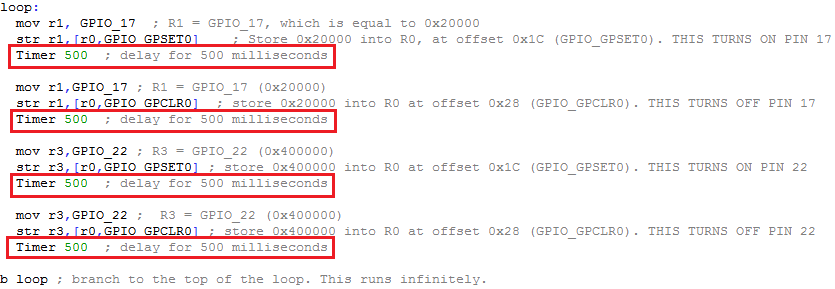
Now that we have the Timer function implemented, we can call on it wherever we want in our program. The GPIO code is from the previous blog and I will not be discussing it. After we turn on or off a GPIO pin, we call the Timer function and pass a value of 500 to it. This tells the program to delay for 500 milliseconds. We could change the 500 to any value we want to cause a delay of however many milliseconds we want. For instance, I could call Timer 2000 to create a delay of 2 seconds. Or I could call Timer 250 to cause a delay of 250 milliseconds, or a quarter of a second.
As you can see, the bulk of our implementation was for the Timer function. Once that function is created, it’s easy to call on it in your code.
Conclusion
Using the hardware timer appears to be more accurate than calculating CPU cycles for computation, which is what I did for my delay function in my first post. When I used the CPU cycle implementation, I struggled to get an accurate timing. This was largely due to L1 cache and branch prediction being disabled by default in an embedded environment. Both these features needed to be enabled for my cycle calculations to properly work. In an embedded system, we want to use as few features as possible since our system will have a very narrow scope of functionality. Having to enable L1 cache and branch prediction is not always preferable.
However, with the hardware timer implementation, I have L1 cache and branch prediction disabled and I can get incredibly accurate timing. This is the benefit of having a dedicated hardware timer that is not tied to the CPU. Additionally, the code is more simplified than my previous implementation. All I do is grab an initial time and the current time and subtract them. I don’t have to calculate the number of cycles per loop and what my CPU clock speed is. I don’t have to enable L1 cache and branch prediction. It’s a much simpler implementation that also provides more accuracy.
Hopefully, this post has been helpful for you. Good luck!
Share this Post