In the world of embedded systems, startup time is important. When you turn on your television, you want to be able to start watching within 5 seconds from the time you press the power button. But how do you create a program that can boot that quickly and not require any other user input to execute? Welcome to the world of embedded systems programming (sometimes called bare metal programming). In this post, I’ll give a simple introduction to creating embedded programs that can run on a Raspberry Pi computer. Do note that this will require some ARM Assembly programming that utilizes hexadecimal and some math involving bytes and bits.
By the end of this tutorial, you will have a Raspberry Pi that, when it boots up, will run a program that blinks two LEDs on and off on a breadboard. It will end up looking like this (not exactly but similar) while it’s running:
(via GIPHY) Essentially, we’ll be creating the same project I did a month ago but in an embedded systems environment.
What are Embedded Systems?
In this post, we’ll be looking to use a Raspberry Pi to accomplish this goal. We’ll need to strip the Raspbian OS off the micro SD card and load some specific files onto the card to enable the Pi’s boot loader to run the program we want. In doing this, we’ll be able to access the Pi’s hardware directly and we’ll see how we can turn two LEDs on and off at regular intervals using GPIO pins. This will allow our Pi to operate as an embedded system. Once the OS is stripped off, we will program the desired functionality using assembly. We will be accessing hardware as per the hardware manufacturer’s specs.
Embedded systems refer to computers that do not have an OS (operating system) and are, usually, designed for a very specific function. When computing was in its infancy, just about every system used the embedded systems because operating systems didn’t exist in any meaningful form. Today, embedded systems are still used for specialized applications. Additionally, embedded programming is used for firmware because of the time benefits. Consider how long it takes your PC or Mac to boot up when you press the power button. Most of this startup time is due to the complexities of the operating system that is being run, either Windows or OS X. Additionally, while you are using a computer in the OS environment, the computer’s hardware is doing lots of work to run the many background processes of the OS.
Embedded systems free you from these performance restraints by getting rid of the OS and running a program directly from the hard drive. This allows your device to boot up in a minimal amount of time and utilize all the performance of your hardware, as necessary.
Of course, this sounds amazing and you might be wondering why every program doesn’t run this way. The answer (mostly) is convenience and the needs of a system. There is a reason computers were not incredibly mainstream until Apple and Microsoft came around. The creation of an easy-to-use, graphically-driven interface allowed everybody easy access to computers. The OS, despite eating performance and having longer load times, was so convenient and useful, that most people, including developers, embraced the benefits. That’s not to say that computers were worthless before an OS was created. Embedded systems were incredibly beneficial prior to the creation of an OS.
Additionally, PCs that run operating systems are, generally, multi-purpose machines. Most people will need to do word processing, spreadsheets, internet browsing, listening to music, watching videos, mathematical calculations, and more. This variety creates a need for more complex systems that utilize a variety of hardware to create a variety of functionality. Embedded systems, in contrast, generally focus on handling a single piece of equipment that has a narrow scope of functionality.
How Do You Program Embedded Systems?
As far as the program goes, it will need to be programmed using ARM assembly. Assembly is the lowest-level, human-readable programming language for a computer. Since we do not have an Operating System in embedded programming, we do not have any fancy compilers that enable us to use high-level languages such as Java, C#, or Python. Instead, we need to use a language that the computer can understand natively.
What we will end up doing is compiling our assembly into our own kernel that the Pi will boot into instead of the normal Raspbian kernel. To accomplish this, we will end up stripping all the data off the Pi’s SD card (Don’t worry – We will back up our data first!) to load our kernel onto it. Typically, a kernel acts as a bridge between hardware and software. The Raspbian kernel makes it easy for us to grab data from the keyboard or monitor and manipulate it, for instance. In an embedded system, however, we don’t need to communicate with most of this hardware. Nor do we need a GUI to make our way around the system. Embedded Designs are usually programmed for a very specific function. In this case, all we want to do is blink two LEDs. Our system will be time-sensitive to boot largely because we will have removed everything that is not critical for making our LEDs blink.
What You’ll Need
To complete this project, you’ll need the following components:
All components (with the exception of a computer, a flat assembler, and GitHub files) are included in the Raspberry Pi 3 Starter Kit.
- 1 – Raspberry Pi (Model 2 or 3 for this tutorial)
- 1 – GPIO to Breadboard interface
- 1 – GPIO ribbon cable
- 1 – 5v Power Supply to power Raspberry Pi
- 1 – Breadboard
- 4 – Male-Male cables (pin-pin)
- 2 – LEDs
- 2 – 330-ohm resistors
- A separate computer that you can write the program on. It must be running Windows or Linux/Unix.
- ARM Flat Assembler Compiler. You can download it here. You need this to make the program. Install it on your separate computer.
- Embedded Programming Files from the Studica Github. Unzip the archive so that you have access to the files.
Procedure
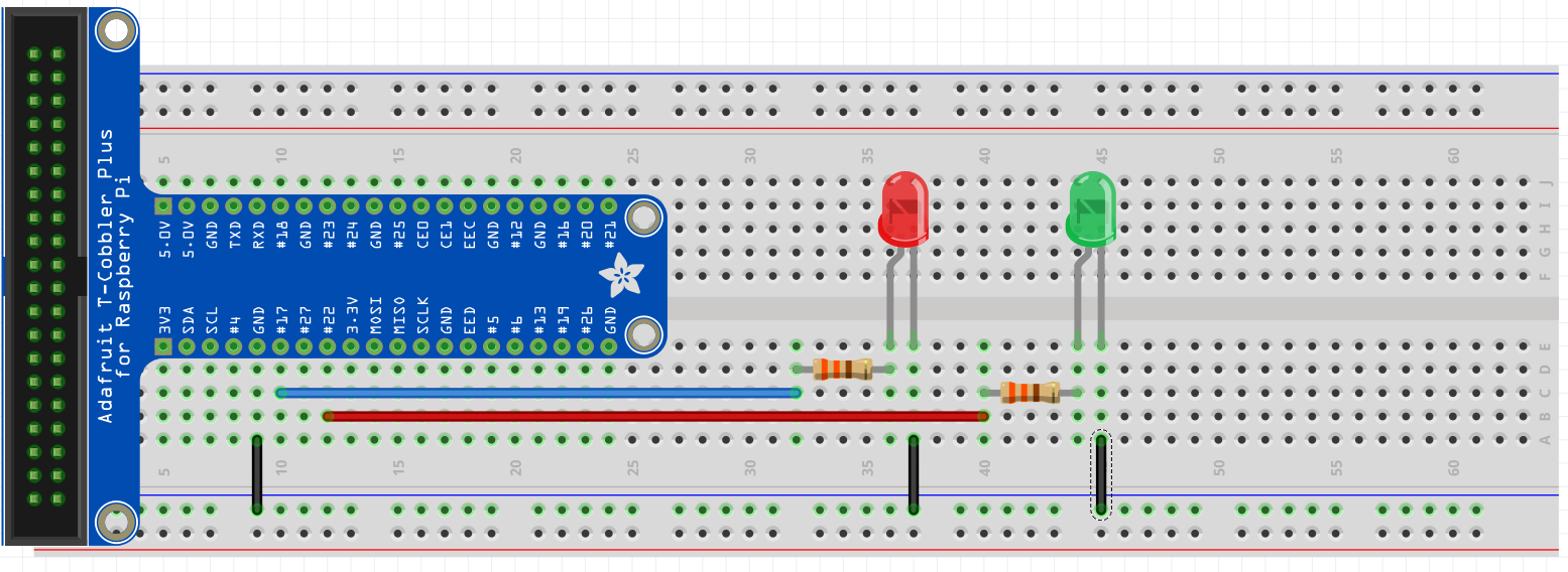
First, wire your breadboard like in the below image.
NOTE: If you have 3v3 rails, do not use them. Use 5v GND for the LEDs.
Wiring a LED requires that you know which lead is positive and which is negative. The longer leg of the LED is the positive lead. See the following diagram.


Schematic
 If you want a more detailed procedure on wiring the board, refer to this post and follow the procedure. Be sure to use pins 17 and 22 instead of 17 and 19 if you follow that post.
NOTE: Anytime you are going to remove the SD card from the Pi, make sure the Pi is turned OFF. This will help avoid data corruption and other issues.
- We need to strip the OS off the Pi. Make sure the Pi is turned OFF and then take the micro SD card out of the Pi and plug it into a micro SD reader.
- Plug the micro SD card into your computer and cut/paste the files into a backup folder on your computer. Basically, backup the current contents of the micro SD card onto your computer. Your Pi SD card should be empty after doing this. If you ever want to run Raspbian on your Pi again, you will need to copy these files back onto the SD card.
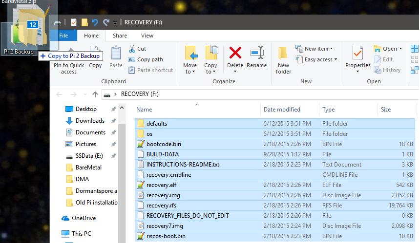

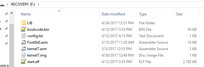
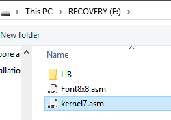
- Grab the Embedded Programming source files from Studica’s GitHub page. You can browse the source or download the .zip file. Extract the files onto your computer and copy the extracted files onto the SD card of the Pi. Your SD card will have this data in it once you’ve successfully done this step:

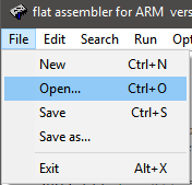
- Go to your FASMARM folder that you downloaded from the link above. Open the FASMWARM.exe file.
- Once FASMARM opens, click File → Browse to your Micro SD card and open the “kernel7.asm” file.


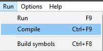
- Once it’s open, you will see the complete code for the project. Go to the Run →Compile option to compile the code out to an .img file. You must do this every time you update the code and want to run the updated code on the Pi.
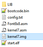
 After doing this, you will see a kernel7.img file on your SD card.

- Remove the micro SD card from your computer and plug it into your Pi.
- Make sure your Pi has a ribbon cable attached from the GPIO pins to the T-board on your breadboard.
- Plug the Pi power supply into the Pi and you should see your two LEDs take turns going on and off.


 After doing this, you will see a kernel7.img file on your SD card.
You’ll notice how quickly your program runs. It takes about 2 seconds for my Pi 2 to start running the program after I plug the power in. The general workflow for writing the code is to repeat steps 5-9 until it works how you want. Remember, every time you want to remove the SD card, make sure the Pi is turned OFF.
How Does the Code Work?
If you are new to ARM assembly, take some time and read over the instruction set. There is also a great ARM Assembly reference on ARM’s website.
The code we will be using is actually very simple. It looks complex but that’s mostly because the assembly syntax is ugly. My code breakdown will consist more of the logic behind what memory addresses to use to enable the functionality we created. Note that I documented the code using comments in the code itself.
Defining Memory Addresses
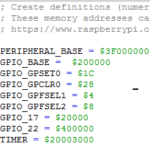


The first thing we are doing is defining memory addresses that we will be using. While it is possible to call the memory addresses directly, it is much more human-readable to define them with clearly written text. This is similar to how definitions work in higher level programming languages like C or C++.
Now, if we want to use PERIPHERAL_BASE in code, we simply call PERIPHERAL_BASE where we need it and it will substitute PERIPHERAL_BASE with $3F000000 without us having to do anything else.
You might be wondering where we are getting these memory addresses from. These addresses are determined by the manufacturer of the hardware and you can find them by referring to their documentation. For the Raspberry Pi 2 and 3, you can reference the Broadcom 2835 documentation. All the memory addresses and specifics about the hardware are in that document.
Delay Function


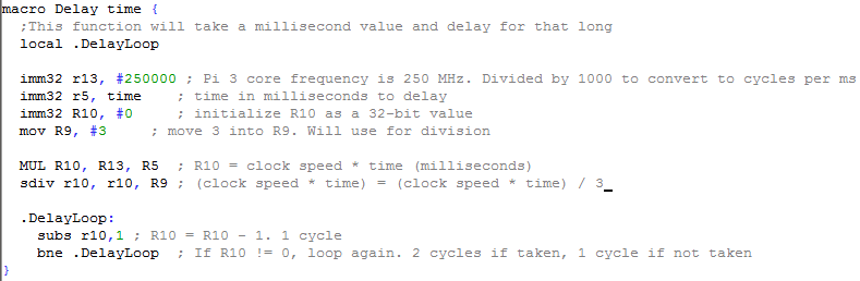
Since we are lacking any fancy timer libraries like you would find in C++ or Java, we are basically creating a delay function that utilizes CPU cycles to pass time. We will do this by counting the cycles a simple no operation loop will take and doing some math against the CPU clock frequency.
First, let’s talk about what macro means. The macro declaration is similar to creating macros in C or C++. The macro declaration allows us to give a syntax for calling the macro, and a functionality to execute when the macro is called. When we write “macro Delay amount”, we’re telling the assembler to recognize “Delay 1000” as a syntax, which will call upon the code that runs within the curly braces. Whatever code exists between the opening and closing curly braces will be executed if the assembler sees Delay x anywhere in the code, where x is a numerical value. So, when we write Delay 500, we’re passing the value of 500 to the code within the Delay function and then executing that code.
Now, let’s look at the actual code. First, we are using 250 MHz as the clock speed because that is the default core frequency that the Pi 3 runs in an embedded systems environment. We get the number of cycles per milliseconds by dividing 250 MHz by 1000. We divide by 1000 because there are 1000 ms in 1 second. This is where we get the value 250000 for the clock speed.
Next, note that the function takes a variable named “time” as a parameter. We store this value into R5 and multiply time by the clock speed of the CPU in milliseconds to get a total number of cycles needed to compute for the time specified. Note that this code seeks to delay by milliseconds not seconds.
Now, we divide the total number of cycles by the number of cycles per loop iteration. We know we have 3 cycles per loop iteration because of the ARM Instruction Set Summary. Using this document as a reference, we can look at each line of code in our loop and determine that we are executing 3 cycles per loop. We divide by this value because we need an iterator to control the execution of our loop. Since our loop has 3 cycles per loop, we divide the total number of instructions to perform by 3, giving us an iterator that will loop exactly the right amount of times to cause a delay.
We then use the iterator value as our loop counter. We will continuously subtract 1 from the loop counter every iteration. Once the number hits 0, we leave the loop. This creates a delay that lasts for as many milliseconds as you passed into the function.
Initialize Cache and Branch Prediction
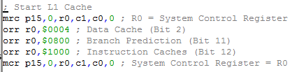

In an embedded environment, it’s important to remember that your code controls almost every aspect of the hardware. Most modern computers make use of caches for fast loading and storing of data. However, the Pi in an embedded environment does not natively have the caches enabled. If we want our delay function to work accurately, we need to enable the L1 cache so our data doesn’t constantly have to take a massive time penalty loading data from RAM all the time.
Additionally, we will want to turn on branch prediction to ensure our loop conditions are using the lowest amount of cycles possible. Branch Prediction, in a nutshell, is a circuit that tries to predict which way a branch will go. It is a critical part of optimizing instruction pipelines.
In the above code, we transfer a coprocessor to R0. We perform bitwise OR computations on the value in R0. The memory addresses, again, are manufacturer-specified and can be found in the Broadcom 2835 documentation. Once we’ve flipped all the bits we need, we load the new R0 data back into the coprocessor. Like magic, this will enable the L1 cache and branch prediction.
Initialize GPIO pins
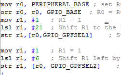

Essentially, we’re creating a memory address based on the memory addresses of the hardware that have been determined by the hardware manufacturer. These memory addresses can be found in the BareMetal\Lib\R_PI2.inc file, contained in the EmbeddedProgrammingBlinkingLEDs.zip you downloaded earlier. Here’s what’s happening, step-by-step:
- Move the memory address of the Pi peripheral into Register 0
- Bitwise OR the Pi peripheral address with the Pi GPIO address. This results in 0x3F200000. We need this so that our code can interact with the proper hardware. If we were using a Pi 1, the Peripheral Address would be different, for instance.
- Move the value of 1 into Register 1. We will use this for Left
- Bitwise Shift Register 1 to the left 21 times. This was one of the most confusing things to me when I started doing embedded systems programming. Why 21? Where did this number come from? Basically, the reason we use 21 is that there are 54 GPIO pins on the Pi. Every 10 pins are broken up into 4-byte sections (32 bits). Within each 4-byte section, every 3 bits represents a GPIO pin. So, to grab GPIO pin 17, we know that it is in byte 4 (Pins 10 – 19). To find out which bit it is associated with in those 4 bytes, we can do some simple math. First, take the base pin that the 4 bytes are associated with. For instance, pin 0, pin 10, pin 20, pin 30, etc. Add a number to it that will add up to the pin number you want. We do not need to code this. This is mental math to help you figure out what value to shift by. 10 + 7 = 17 (I choose 10 because I want GPIO 17. So, I start with 10 and add 7 to it.) 7 * 3 = 21 (Our pin offset is 7 for GPIO 17. Take 7 and multiply it by 3 because each pin is found at every 3 bits in the 4-byte memory) When we left shift the #1 by 21 bits, we will be grabbing the memory address of GPIO 17. If we wanted to grab pin 4, for instance, we would do the same thing. The only difference is that you start at the first pin number associated with the 4-byte sequence. In the case of GPIO pin 4, that number is 0 (because it is part of the 0 – 9 bank of pins):0 + 4 = 4 (GPIO 4) 4 * 3 = 12 Now we know to left shift #1 by 12 to grab the memory address of GPIO pin 4. The Broadcom BCM2835 documentation can be found here. Page 89 is where the GPIO details start. If you find yourself interested in the GPIO hardware, I recommend looking at that document.
- After the left shift, we store the left-shifted value into our previous R0 value. We use an offset value of GPIO_GPFSEL1, which is memory address 0x4. Essentially, we are setting some bits in our memory address at R0 that will allow us to send a signal to GPIO pin 17. But why are we using GPIO_GPFSEL1? Why not GPIO_GPFSEL0 (0x0) or GPIO_GPFSEL2 (0x8)? This is because of what I mentioned in step 4 about the memory addresses of GPIO pins. We know that GPIO 17 is in the second block of 4-byte GPIO data. But remember that computers use 0 as a first index. So instead of GPFSEL0, we use GPFSEL1 to specify the second block of 4 bytes.Pins 0 – 9 are part of memory address 0x0, 10 – 19 are at 0x4, 20 – 29 are at 0x8, 30- 39 are at 0xC, etc. If we were to store our left-shifted R1 value into memory 0x0, for instance, we would instead be using GPIO pin 7, not 17.
- Now we initialize pin 22. Again, move the value of 1 into register 1.
- Bit shift the #1 to the left by 6 bits. Remember: 20 + 2 = 22 (GPIO 22) 2 * 3 = 6 (Value to shift by)
- Store the shifted value into our R0 data containing all our memory addresses. For this pin, we use GPIO_GPFSEL2 (0x8) because our pin is GPIO 22, which falls between 20-29, which is associated with memory address 0x8.
Turning LEDs On and Off
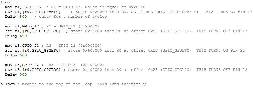

- We initialize the loop with the “loop:” label. This will allow us to use a branch statement to send program execution back to the loop. We’ll use this to create an infinite loop.
- Move the memory address of GPIO_17 into Register 1
- Store GPIO 17’s memory address into R0 at the offset of GPIO_GPSET0 (0x20). This memory address tells the Pi to turn on the GPIO pin, which we set up as an output earlier.
- Delay execution for 500 ms.
- Put GPIO_17 into R1 again.
- Store GPIO 17’s memory address into R0 at offset GPIO_GPCLR0 (0x28). This address tells the Pi to turn off the GPIO pin.
- Everything after this point is the same code except it’s using a different GPIO pin.
- Lastly, we create an infinite loop by branching back to the loop label.
Conclusion
This is an incredibly simple introduction to embedded systems programming on the Raspberry Pi. Unfortunately, this realm of computer science is not well documented. You will do a lot of experimenting to figure out what you’re doing. However, hopefully, this post on has helped provide you with a better understanding of embedded systems, resources, and some basic knowledge to help get you started.
Happy Coding and Good Luck!
Share this Post