Today, we’ll be looking at how we can use the Raspberry Pi to turn light emitting diodes (LEDs) on and off. This is one of the most basic things you can do with a Raspberry Pi but it’s a great starting point for learning about physical computing. By the end of this tutorial, you will have a Raspberry Pi that runs a Python program that will turn two sets of LEDs on and off in an infinite loop.
What is a Raspberry Pi?
![]()
![]() If you are reading this post, you probably already know what Raspberry Pi is. But here’s a quick summary for those who may be new to this system. Essentially, the Raspberry Pi is a small, cheap, fully usable computer. It uses an ARM CPU, which is designed to draw minimal power to run. This allows the Pi to run itself using only 5 volts. The trade-off is that the Pi’s CPU does not have a very fast clock rate. For instance, the Pi 3 has a 1.2 GHz clock speed. Compare that to Intel’s i3 series of processors. You’ll struggle to find one that runs lower than 3 GHz. However, the i3 processor, by itself, is more expensive than the entire Raspberry Pi.
If you are reading this post, you probably already know what Raspberry Pi is. But here’s a quick summary for those who may be new to this system. Essentially, the Raspberry Pi is a small, cheap, fully usable computer. It uses an ARM CPU, which is designed to draw minimal power to run. This allows the Pi to run itself using only 5 volts. The trade-off is that the Pi’s CPU does not have a very fast clock rate. For instance, the Pi 3 has a 1.2 GHz clock speed. Compare that to Intel’s i3 series of processors. You’ll struggle to find one that runs lower than 3 GHz. However, the i3 processor, by itself, is more expensive than the entire Raspberry Pi.
The Pi also has a 3.5mm audio jack, an HDMI output, 4 USB inputs, a 10/100 ethernet jack, and built-in Bluetooth. The Pi 3 also has a built-in wireless card. Probably the most important feature that people purchase Raspberry Pi’s for is the Broadcom BCM2837, which allows you access to 40 pins, many of which can be used as inputs and outputs for wiring sensors or sending power to objects such as LEDs. If you want to know more about the BCM2837, refer to the specifications tab on our Raspberry Pi 3 product page.
What You’ll Need for This Tutorial
- 1x Raspberry Pi (any model should work)
- 1x GPIO to Breadboard interface
- 1x GPIO ribbon cable
- 1x 5v Power Supply to power Raspberry Pi
- 1x Breadboard
- 4x pin-pin cables
- 3x LEDs
- 2x 220-ohm or slightly lower/higher resistors
- Mouse and Keyboard to hook up to Pi
- Monitor to hook your Pi up to.
You can get all the necessary components for this tutorial from our Raspberry Pi 3 Starter Kit.
Wiring the Breadboard
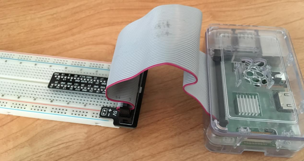
First, I’m going to assume you already have your Pi setup and installed with whatever Unix-based distribution you’re using. I’m also going to assume you have your ribbon cable hooked into your PI’s GPIO pins and connected to your GPIO to breadboard interface, which is plugged into a breadboard.
Your Pi should look something like this (your GPIO to breadboard interface may look different than mine but that shouldn’t be a problem. Your case might also look different. Or you may have no case at all!):

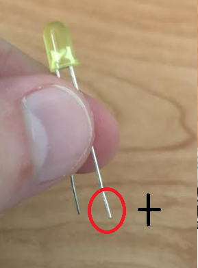
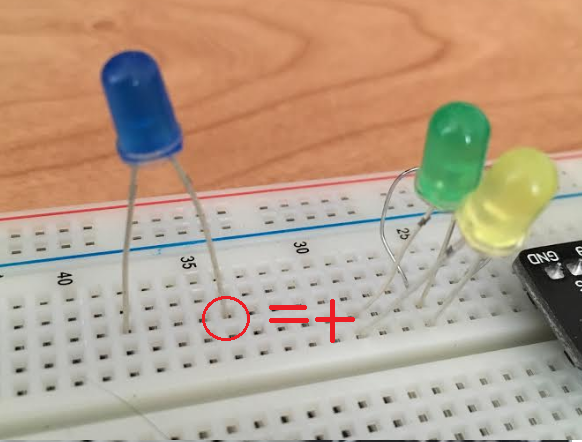
- We need to put our LEDs where they need to go. Take one of your LEDs and plug it into the breadboard. Keep in mind that LEDs have one leg that is longer than the other. This longer leg is where positive ( + ) voltage connects.

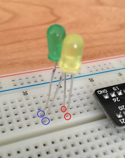
- Take a second LED and plug it in parallel to the first LED, as seen here:

- We need to add a 220-ohm resistor to this circuit so the LEDs don’t burn out from the voltage of the Pi. The Starter Kit Studica offers comes with 330-ohm resistors. These resistors should work as well, but your LEDs won’t shine as brightly. Plug one leg of the resistor into an empty row of the breadboard and connect the other leg into the row that the positive LED legs are in.
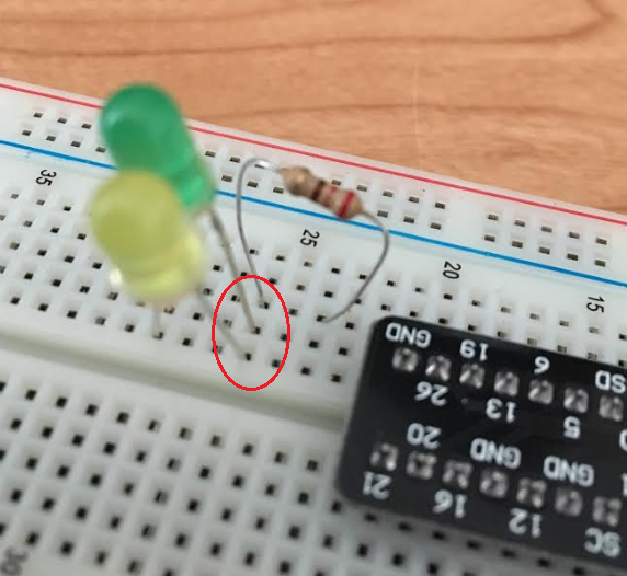

- Now let’s plug in our third LED separately from the parallel circuit. Remember, the long leg is the + input.

- Let’s add another resistor to this LED. Plug one leg of the resistor into an empty row and the other leg into the row the + LED leg is in.
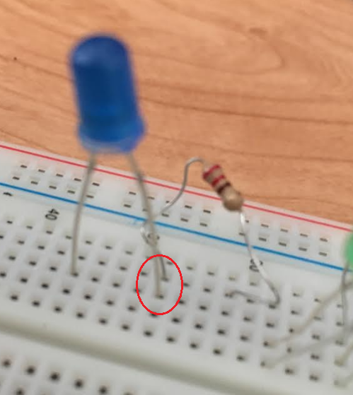

- Let’s add another resistor to this LED. Plug one leg of the resistor into an empty row and the other leg into the row the + LED leg is in.

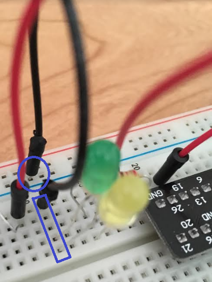
- Plug a pin into GPIO 19. Plug the other end of the cable into the row with the resistor leg that is NOT connected to the 3rd This will allow us to send a high or low signal through GPIO 19 to turn on or off the third LED. In the below image, the pins with red circles around them belong to the same cable.

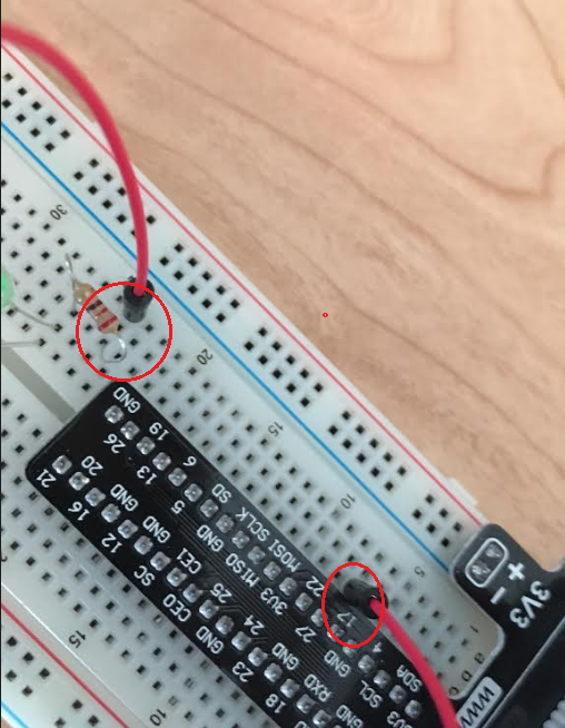
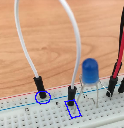
- Now we need to plug in our ground cables to complete our circuits. Take a pin-pin cable and plug one end into the 3v negative column of the breadboard. Plug the other end of the pin into the row of the parallel LEDs short legs (their ground legs).

- Now do the same thing for the third LED. Plug another cable into the 3v Negative column and plug the other end into the 3rd LEDs resistor leg that is not connected to anything.


That’s all there is to our breadboard setup. Now, we need to do some programming on our Pi so we can control the LEDs.
Programming
As mentioned above, the reason we have cables running from the GPIO pins of the breakout board is so the Pi can send a voltage to whatever the GPIO pin is connected to. This is a large reason the Raspberry Pi is excellent for physical computing. What we will need to do is write a Python (or C) program that can make use of the Raspberry Pi libraries to send a signal to our LEDs to turn them on and off.
For this tutorial, I used Python, but you could also use C if you wanted to. If you want to use C, I recommend looking up the lwiringPi.h header file.
First, you should make sure your Raspbian is up-to-date and that your firmware is up-to-date. To do this, plug your Pi into a monitor and connect a keyboard and mouse to it. Once the Pi is booted up, make sure you are connected to the internet and then open the Terminal application. Once the terminal is open, run these commands individually.
sudo apt-get update
sudo apt-get upgrade
sudo rpi-update
Each of these commands may take a while to execute depending on various factors. These commands should get your software and firmware up-to-date.
Once this is done, follow these steps.
- In the terminal, type sudo nano LedLoopDemo.py and press enter. Note: You can use whatever text/code editor you want. Just change nano in the above command to whatever editor you want to use.


- Once the program is open, refer to the below code. Feel free to copy and paste it. You can find the code on my GitHub.
- Once the code is created, save the file and exit back to the terminal.
- Run the command sudo python LedLoopDemo.py and press enter. You should now see your LED lights turning on and off one after another. You can exit the program by pressing ctrl + c.


That’s all there is to it! The code is documented so you should be able to make sense of it. Try messing with some of the variables and see what you can do. If you want to see more complex code that allows a user to turn lights on and off using input, see This Code.
Your project should look like this while it’s running.
Conclusion
That’s all there is to it. Hopefully, you see how the Raspberry Pi can be used to do some pretty cool things. It becomes, even more, fun when you start using sensors for inputs and outputs. Happy computing!
Be sure to check out Studica.com for academic discounts on software, electronics, robotics and more. Sign up for Studica’s email newsletter* for even greater savings!
Blogger: Mark Philipp, Application Engineer at Studica
Share this Post