Quick Summary: This article walks FTC teams through everything needed to program a mecanum drivebase using the FTC Drive Base Kit from Studica Robotics. You’ll learn how mecanum wheels work, how to configure motors in the Driver Hub, build a working TeleOp program, create a basic autonomous routine, and improve performance through tuning techniques like dead zones and input scaling. Whether you’re new to FTC or refining your drivetrain, this is a practical, team-ready resource for building smoother, more precise robot control.
Mecanum Drive Programming Fundamentals
Mecanum drivetrains are one of the most powerful and flexible systems used in FTC robotics. When programmed correctly, they allow your robot to move in any direction – forward, backward, sideways, and rotationally – all independently.
This article is designed to help teams using the Studica Robotics FTC Drive Base Kit, though the concepts apply to any FTC mecanum drivetrain. For this tutorial, we’ll use a mecanum drivebase built with the mecanum wheel set from Studica Robotics, along with an FTC Control Hub, Driver Hub, and a standard FTC-legal gamepad. All programming will be done in Blocks through the Control Hub’s web-based interface.
How Do Mecanum Wheels Work?
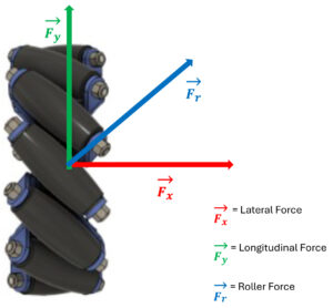
Force Diagram of Mecanum Wheel
Mecanum wheels use rollers positioned at a 45° angle. Instead of pushing straight forward like traditional wheels, each wheel produces a diagonal force vector.
That force can be broken into:
- Fy → Forward and backward motion
- Fx → Sideways (strafing) motion
A single wheel alone isn’t very useful, but when all four wheels work together, those forces combine and cancel in specific ways to create controlled movement.
Correct Mecanum Wheel Configuration
A mecanum wheel has angled rollers that create force vectors at 45 degrees. When these forces combine across four wheels, the robot can move forward, backward, sideways, or rotate.
The “X” wheel configuration:
- Forces cancel or combine depending on the direction of travel
- Forward motion cancels sideways forces
- Strafing cancels forward forces
- Rotation creates torque around the robot’s center
This is what makes mecanum drivetrains holonomic, allowing full directional movement without turning first.
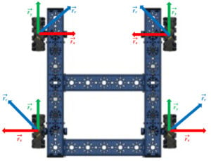 Force Diagram of Each Wheel in a Mecanum Drivebase |
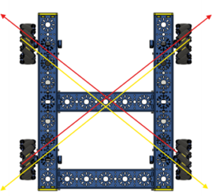 X Pattern of Wheels in a Mecanum Drivebase |
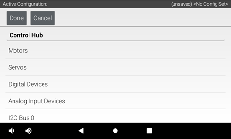
Hardware Setup (Driver Hub Configuration)
Before coding, you must configure the robot hardware in the FTC Driver Station. This tells the Control Hub which ports each electrical device, such as motors, servos, and sensors, is connected to.
Accessing the Configuration Menu
1. Power on the Control Hub and Driver Hub.
2. Open the Driver Hub and connect to the Control Hub.
To get to step 3, teams would need to open the Drive Station App built into the driver hub.
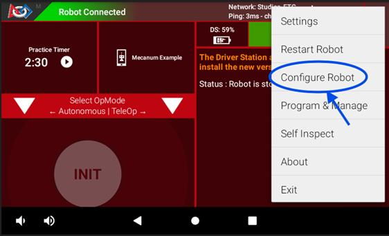
3. Tap the three dots (⋮) in the top-right corner.
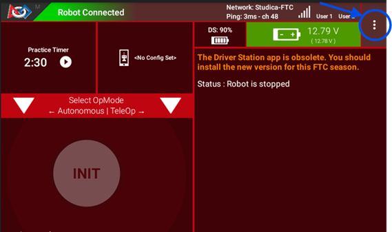
4. Select Configure Robot.
Create a New Configuration
1. Tap “New”
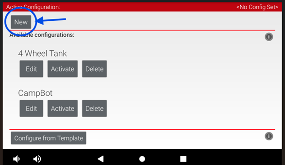
2. Select your hardware type (Control Hub) and click on the “Control Hub Portal”
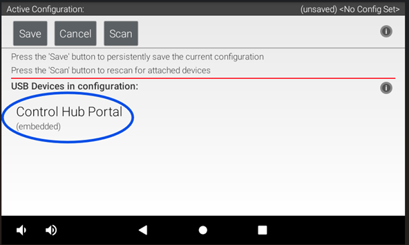
3. You will see a list of available ports.
How to Assign Motors to Ports
1. Tap on a Motor Port (example: Port 0)
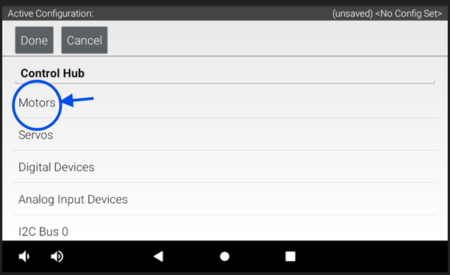 2. Assign each motor port to the correct motor and name each motor
3. Name the motors based on the drivetrain’s perspective (front, back, left, right).
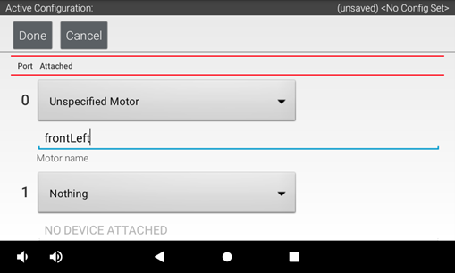
For this configuration, our motors are labeled as:
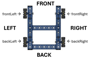
| Motor Name | Port |
|---|---|
| frontLeft | 0 |
| frontRight | 1 |
| backLeft | 2 |
| backRight | 3 |
Tip: Use consistent directional names like frontLeft, frontRight, backLeft, and backRight. This prevents confusion later in programming.
TeleOp Programming (Driver Control)
The example TeleOp program shown below uses a simple block-based structure, making it easy to map driver inputs directly to robot movement controls. The information in this section introduces the key concepts you’ll need to understand before working through the drag-and-drop version of the program.
Control Mapping and Motion
Use the following control mapping as a reference for robot movement.
The left joystick controls forward/backward and strafing, while the right joystick controls rotation.
| Motion | Controller Input | Axis |
|---|---|---|
| Forward / Backward | Left stick up / down | Y-axis |
| Strafe | Left stick left / right | X-axis |
| Rotation | Right stick left / right | Z-axis |
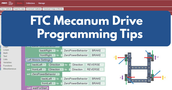
Motor Behavior Setup
Before writing any movement logic, the drivetrain motors need to be configured so they respond correctly during operation.
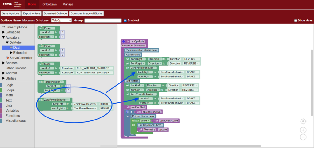
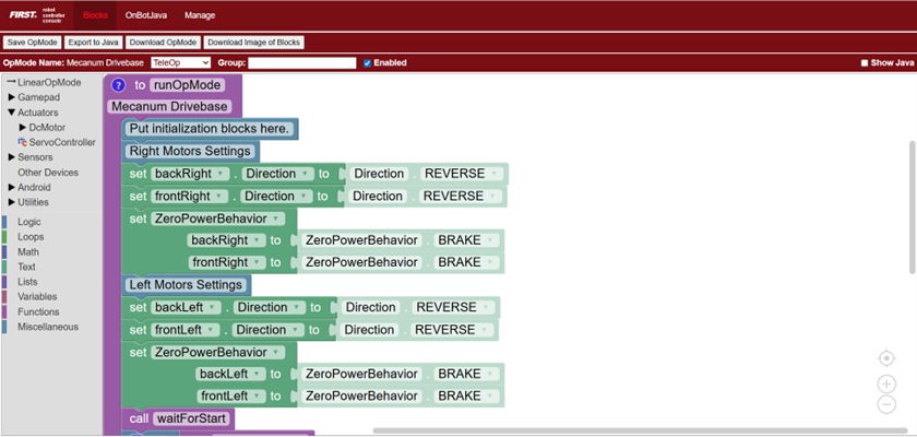
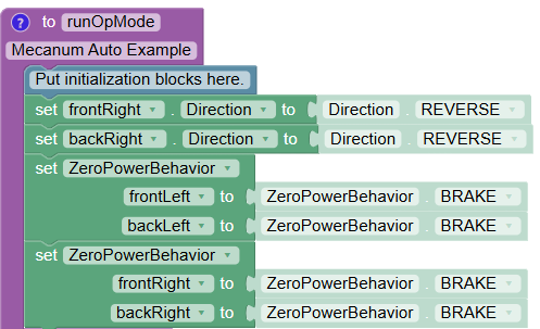
Motor Direction
Because the motors on opposite sides of a mecanum drivetrain face opposite directions, one side must be reversed. This ensures that when the robot is commanded to drive forward, all four wheels spin together in the correct direction.
Here is the code showing motor direction configuration, where one side of the drivetrain motors is reversed so all wheels rotate correctly for forward movement. This code determines how motors will behave when not powered.
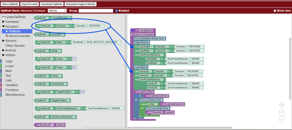
Zero Power Behavior
Zero Power Behavior determines how the robot responds when no power is being applied. Setting this to BRAKE causes the motors to stop immediately and hold their position when the driver releases the joysticks. The drivetrain will stop immediately and try to hold its position. This provides more precise control during TeleOp.
Here is the code setting drivetrain motors to BRAKE mode, causing the robot to stop immediately and resist rolling when joystick input returns to zero.
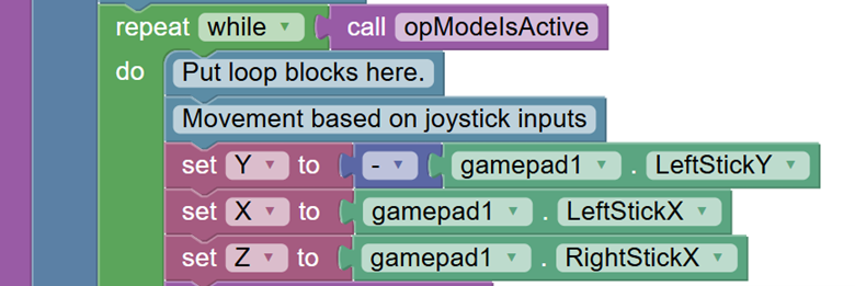
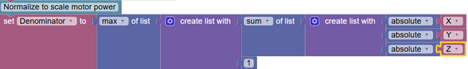
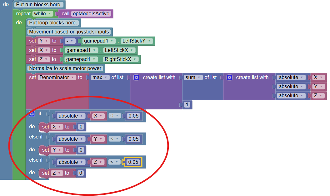
Declaring Variables
Next, create the variables that will control robot movement. These variables represent the three primary directions of the mecanum drive, along with a scaling value used to normalize motor power.
- Y → Forward and backward movement
- X → Side-to-side strafing movement
- Z → Rotation left and right
- Denominator → Scales motor powers proportionally so no value exceeds the allowed range, ensuring smooth and accurate movement
Here, the code is creating variables for mecanum drive control, including forward/backward, strafing, rotation, and motor power normalization.

Why Normalizing Motor Power Matters
When multiple joystick inputs are combined, motor power values can exceed the allowed range of -1.0 to 1.0. Normalization scales all motor values proportionally so the strongest motor runs at full power while preserving the intended direction of movement.
Without normalization, motor values are clipped, which causes uneven power distribution and unpredictable motion.
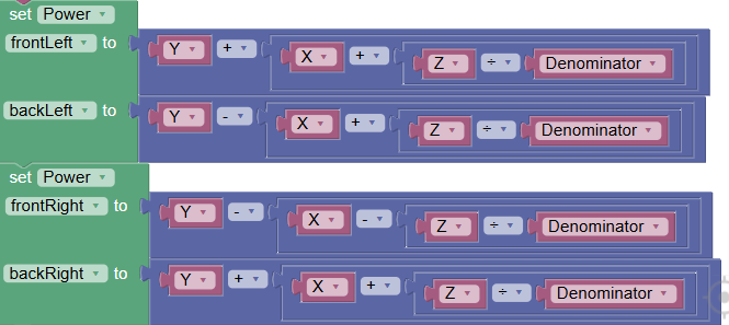
Mecanum Motor Power Equations
Each wheel receives a combination of X, Y, and Z values. These equations determine how forces combine to produce omnidirectional movement.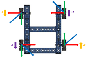
- frontLeft = Y + X + Z
- backLeft = Y − X + Z
- frontRight = Y − X − Z
- backRight = Y + X − Z
Each value is then divided by a normalization factor when necessary.
Why This Works
- Y controls forward and backward movement.
- X controls sideways strafing.
- Z controls rotational torque.
Because each wheel contributes differently, combining these inputs creates full omnidirectional motion.
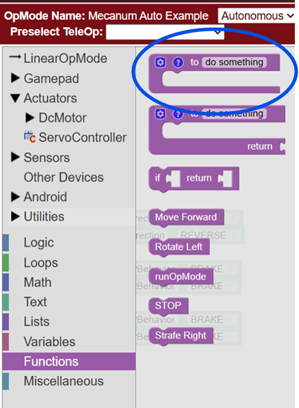
Autonomous Programming
Before diving into the full autonomous example, it’s important first to understand the foundation of Autonomous Programming in FTC. This section begins with Initialization and Calling Functions, which set up how the robot’s motors and systems will behave before any movement starts. Defining motor behavior early ensures your autonomous runs accurately and consistently, while clearly structuring functions helps you understand what each part of your code is responsible for before putting everything together into a complete autonomous sequence.
Initialization
As previously demonstrated in the TeleOp example, set the motor direction so that the all the wheels move in the same direction to drive forward. Then set the motors so that all the wheels brake when motor power = 0
Calling Functions
For this autonomous example, each movement of the robot is separated into its own function. A function is a reusable block of code to perform a specific task. So instead of repeatedly writing the same motor commands, you can group them into a single function and call those commands whenever needed.
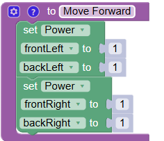
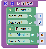
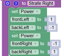
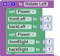
Create the following functions below. These functions define the motor outputs to perform each movement. The “STOP” function sets all motor power to zero, ensuring the robot halts before executing the next action
Basic Autonomous Example
Autonomous code runs sequentially from top to bottom. Each block is executed in order, one after another.
A simple FTC autonomous routine often begins with timed movements. Here is an example flow:
- Move forward (1.5 seconds) – Here is a code example:
- Stop (1 second) – Here is a code example:
- Strafe right (0.5 seconds) – Here is a code example:
- Stop (1 second)
- Rotate left (1.5 seconds) – Here is a code example:
- Stop
This approach is ideal for beginners before moving to encoder-based autonomous programming.
The complete code would look like this:
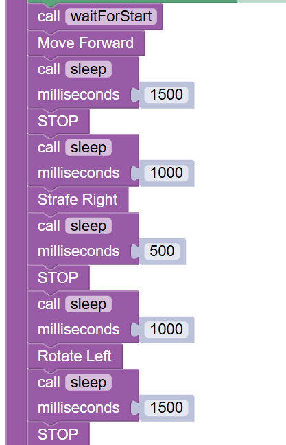
The block of code above has each function combined to perform a simple timed autonomous routine. After the robot is started, the code calls the “Move Forward” function, which has the robot drive forward for 1.5 seconds, then stops for 1 second before moving onto the next function. The robot then strafes to the right for 0.5 seconds after the “Strafe Right” function is called, then stops for another 1 second. Then the “Rotate Left” function is called and the robot rotates for 1.5 seconds before stopping completely to end the routine.
Improving Control and Tuning
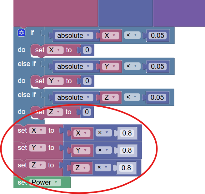
1. Deadzone (Fix Stick Drift)
Deadzones prevent unintended motion when the joystick is near zero.
- Helps eliminate drift
- Improves stability at rest
Tradeoff: Too large of a deadzone can reduce fine control.
2. Input Scaling
Input scaling reduces maximum speed for better precision.
- Example: 1.0 × 0.8 = 0.8
- Makes the robot easier to control
Tradeoff: Lower maximum speed.
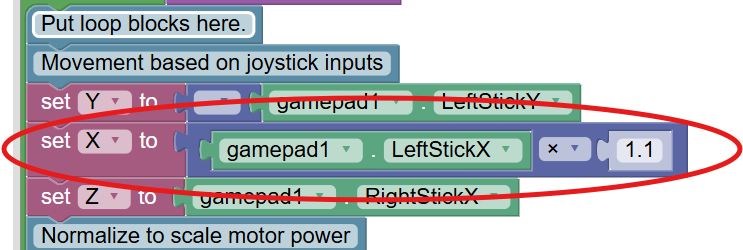
3. Strafe Compensation
Mecanum wheels are typically less efficient when moving sideways than forward.
Slightly increasing the X input can improve balance between strafe and forward speed.
Troubleshooting Common Programming Issues
Here are some common issues FTC teams face when programming their mecanum chassis, along with helpful tips to fix them.
| Issue | What to Check / Fix |
|---|---|
| Robot moves incorrectly | Verify the motor direction settings in the code and ensure the motors are mapped correctly. |
| Robot drifts | Confirm proper normalization is implemented and check wheel alignment. |
| Strafing doesn’t work | Ensure mecanum wheels are installed in the correct “X” pattern and motor mapping matches your code. |
| Motors behave inconsistently | Use telemetry to monitor joystick inputs and motor outputs in real time. |
Telemetry (Your Best Debugging Tool)
Telemetry helps teams debug by showing live data from the robot while the code is running. Instead of guessing what the robot is doing internally, telemetry lets you see exactly what the robot thinks is happening in real time.
In FTC programming, you typically use telemetry during testing to compare what you expect the robot to do with what it is actually doing. If something looks wrong, telemetry helps you narrow down whether the issue is coming from the controller inputs, your code logic, or the motors themselves.
Telemetry Debugging Overview
Here are some of the most common things teams use telemetry to check:
| Debug Area | What It Shows | How It Helps |
|---|---|---|
| Joystick inputs (X, Y, Z) |
Gamepad values (-1 to 1) for each stick axis | Confirms controller inputs are being read correctly and helps identify mapping or control issues |
| Motor output values | Real-time power sent to each motor | Verifies drivetrain math, motor direction, and whether power is being applied correctly |
| Real-time robot behavior | Key variables like drive mode, speeds, or sensor data | Helps you understand what the robot is doing while running and isolate logic vs hardware issues |
This is one of the most valuable debugging tools in FTC programming because it turns invisible code behavior into clear, readable information you can act on immediately.
Where Studica Robotics Fits In
 The Studica Robotics FTC Drive Base Kit is designed to make mecanum programming easier by providing:
- Pre-engineered drivetrain geometry
- FTC-compatible motor configuration
- Consistent mechanical alignment for smoother strafing
- A reliable starting point for learning drivetrain programming
This allows teams to focus less on mechanical inconsistencies and more on learning core robotics concepts like kinematics, control systems, and autonomous design.
Frequently Asked Questions
What is mecanum drive in FTC?
Mecanum drive is a holonomic drivetrain that allows a robot to move in any direction without turning first.
Why do FTC teams use mecanum wheels?
They provide full directional movement, making scoring, alignment, and positioning faster and more efficient.
Why is my mecanum robot drifting?
Common causes include incorrect motor direction, missing normalization, joystick drift, or mechanical misalignment.
Do I need to normalize motor power?
Yes. Without normalization, combined inputs can exceed motor limits and cause unpredictable movement.
What is the best way to learn FTC mecanum programming?
Start with TeleOp control, then add tuning features like deadzones and scaling. Once you’re comfortable, move on to encoder-based autonomous routines.
Conclusion
Programming an FTC mecanum drivetrain is one of the most important skills for competitive robotics teams. Once teams understand how forces combine across all four wheels, they can unlock smooth omnidirectional movement, precise driver control, and reliable autonomous performance.
With the Studica Robotics FTC Drive Base Kit, teams gain a strong mechanical foundation, allowing them to focus on what really matters: writing smarter code, improving control, and building better autonomous strategies.
Share this Post