


How to Build a Mecanum Drivetrain Robot Instructions
Mecanum Drivetrain Building Guide: How to Build a Mecanum Chassis
The FTC Drive Base Kit – v2 from Studica Robotics includes all the parts needed to complete this Mecanum drivetrain build. This kit is available at https://www.studica.com/studica-robotics/ftc-drive-base-kit-v2
These build instructions will walk you through the steps of building a Mecanum Drivetrain. View as a PDF.
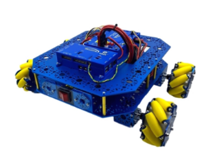
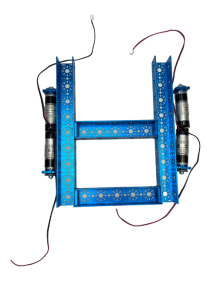
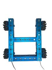
(Also referred to as a Mecanum Chassis or Mecanum Drive Base.) This is an example of what your completed project will look like.
Summary of Content:
- Parts List:
- Structure
- Motion
- Screws, Nuts, Spacers
- Mecanum Drivetrain Building Instructions:
- Frame Assembly
- Motion Components
- Final Assembly
- Code for FTC (Onbot Java)
Parts List:
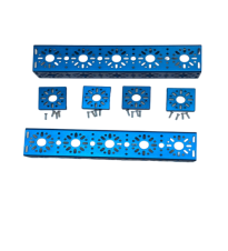
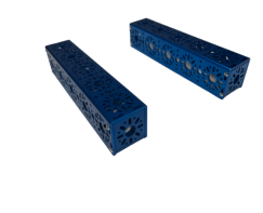
Structure:
Description | Part # | Quantity |
432 mm U-Channel
|
| 2 |
240 mm U-Channel
|
| 2 |
End Piece Plate (2 pack)
|
| 2 |
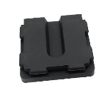
U-Channel Bumper
|
| 1 |


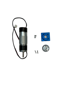
Motion:
Description | Part # | Quantity |
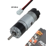
NeveRest Orbital Gearmotor JST-VH-2
|
am-3637b | 4 |
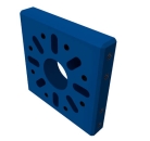
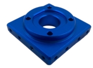
Orbital Mount Plate
| 4 | |
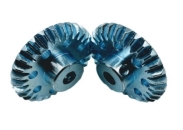
30 Tooth Bevel Gear (2 Pack)
| 4 | |
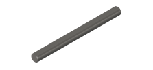
6mm x 70mm D-Shaft (6 pack)
| 1 | |
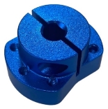
Clamping Shaft Hub
| 4 | |
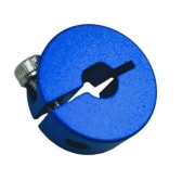
6mm D-Shape Collar Clamp
| 4 | |
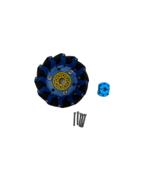
100mm Slim Mecanum Wheel Set (Bearing Rollers, 2 left, 2 right) | 1 |
Screws, Nuts, Spacers:
Description | Part # | Quantity |
M3 x 6mm Socket Head Cap Screw (50 pack)
| 1 | |
M3 x 10mm Socket Head Cap Screw (100 pack)
| 1 | |
M3 x 12mm Socket Head Cap Screw (100 pack)
| 1 | |
M3 x 25mm Socket Head Cap Screw (50 pack) | 1 | |
Shaft Spacer Plastic 6mm ID x 10mm OD x 1mm L
| 1 |

Mecanum Drivetrain Building Instructions:
Frame Assembly:
- Screw the 2 End Piece Plates to each of the 240mm U-Channels using the M3 x 10mm Socket Head Cap Screws
- Screw the 240mm U-Channels to the 432mm U-Channels using the M3 x 10 mm Socket Head Cap Screws
- The 240mm U-Channels should be placed on the end and center of the 432mm U-Channels (Center being the fifth hole pattern from the end)

- The 240mm U-Channels should be placed on the end and center of the 432mm U-Channels (Center being the fifth hole pattern from the end)
Motion Components:
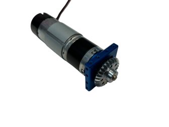
- Screw the motors onto the Orbital Mount Plate using the M3 x 10mm Socket Head Cap Screws
- Attach one of the 30 Tooth Bevel Gears to the shaft of the motor and tighten.
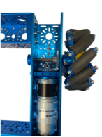
- Secure the Orbital Mount Plate to the 432mm U-Channels using four M3 x 6mm Socket Head Cap Screws on each plate.
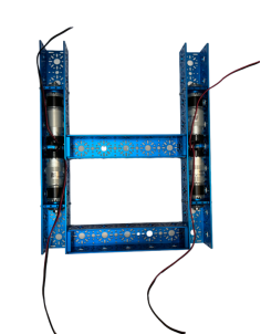
- Motors should recess in the 432mm U-Channels as shown in the image.
- Screw the Clamping Shaft Hub to the 100mm Slim Mecanum Wheels using six M3 x 25mm Socket Head Cap Screws for each wheel.
Final Assembly:
- Place Flange Bearings onto the 432mm U-Channels where the shafts will be inserted, on the hole pattern adjacent to the Bevel Gear attached to the motor’s shaft.
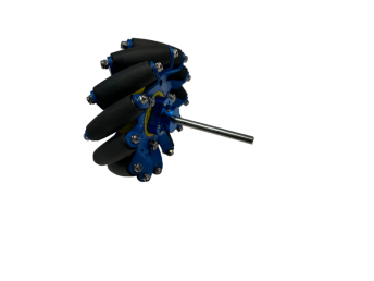
- Insert the 6mm x 70mm D-Shaft into the Clamping Shaft Hub so it is about flush with the shaft.
- Insert the 70mm D-Shaft through the Flange Bearings and 30 Tooth Bevel Gear on the 432mm U-Channel
- Before tightening the set screws for the Bevel Gears, make sure the driving gear on the motor shaft and the driving gear on the wheel shaft mesh with one another.
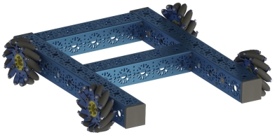
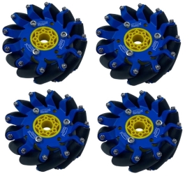
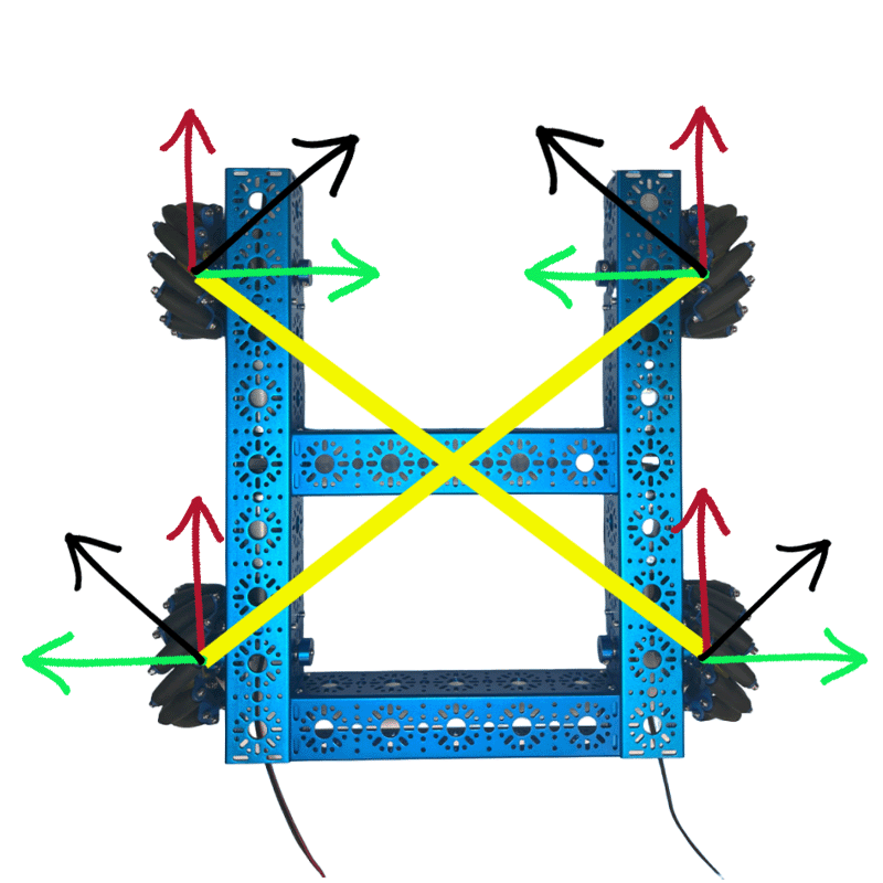
- The wheels of the drivebase should be oriented like the image below. The rollers should be angled towards the center of the robot in an “X” pattern. This is so the drivebase can drive in as well as perform rotations about its center of mass.
- Place the 6mm D-Shape Collar Clamp on the end of the 6mm x 70mm D-Shaft and secure it by tightening the clamp with the given set screw.

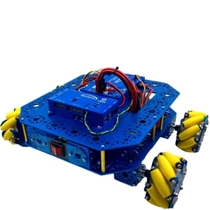
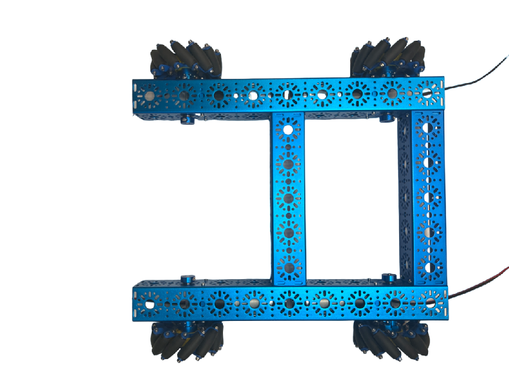
Your build should look like this:

Code for FTC (Onbot Java):
Below is the code for the FTC Drive Base Kit – v2 in Onbot Java for FTC. The variables “x”, ‘y”, and “rx” represent the 3 axes of movement in the mecanum drive base. The left stick controls the x and y-axis movement (forward, backward, and strafing left to right). The denominator variable is the absolute value of the largest motor power or 1. This is to maintain the power ratio between -1 and 1. (View PDF for clearer coding instructions.)