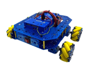
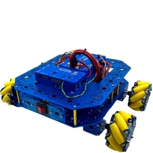
Build Guide: How to Build a Robot with the STEM BOT Pro Kit
The STEM BOT Pro Kit allows students to explore the possibilities of STEM and mobile robotics in various applications from basic to advanced concepts.
These build instructions will walk you through the steps of building the STEM BOT Pro robot.
Download to View STEM BOT Pro Build Guide as a PDF.
Download to View STEM BOT Pro Kit Parts List as a PDF.
About the VMX Robotics Controller
As the “brain” of a robot, the VMX Robotics Controller is a powerful, versatile Linux-based robot controller that offers compatibility with programming languages including Java, C++, Python, and LabVIEW, along with support for ROS. Integrated with the NavX-IMU and combined with the Titan Quad Motor Controller, the VMX acts as the powerful “brain” of your robot. Capable of programming for both tele-operated and autonomous controls. It also houses an integrated NavX IMU (Inertial-Measurement-Unit) for advanced movement performance in tele-op and autonomous driving.
Helpful Resources: Example of Code used for the VMX
This guide will go over an example project from Studica Robotics github, using the VMX. The example code can be found here: https://github.com/studica, in the WorldSkills-Example-Projects repository under the Popular Repositories.
Troubleshooting for VMX: Updating Firmware
Certain cases may require the firmware to be updated for the VMX to improve functionality or fix any bugs. To do so, use the following instructions on our WorldSkills resources page: https://docs.wsr.studica.com/en/latest/docs/VMX/update.html
A firmware update should be performed in case there are any issues with deploying your project to the VMX or issues with the connection between the driver station app and the VMX/Titan.
VMX: Channel Block
Connector Block | Connector Type | Location on VMX |
Flex DIO Header | 3-pin PWM-style | Left-side Top |
High Current DIO Header | 3-pin PWM-style | Left-side mid |
Analog Input Header | 3-pin PWM-style | Left-side bottom |
Comm DIO Connectors | 4-pin JST GH | Bottom-left |
Flex DIO Connectors | 4-pin JST GH | Bottom-middle |
CAN Connector | 2-wire Weidmuller | Bottom-right |
About Titan Quad Motor Controller:
The Titan Quad Motor Controller is a 4 channel CAN-based motor controller. Combined with the VMX, the Titan acts the Power Distribution Panel (PDP) for your robot, primarily for the VMX.
Titan: Map of Ports and Inputs
1. Power input. Input requires a 12VDC battery, and two ports are available connected in parallel. Both ports can be used for increasing the capacity or as a battery in, battery out.
2. Power output. Outputs 12VDC out to other devices such as, VMXpi or Servo Power Block.
3. Voltage indicators. There is a reverse power indicator (red) that will light up if the voltage is connected in reverse. The other two indicators display the voltage rails 5V and 3.3V.
4. Fusebox. Before voltage can be applied to the motors or power outputs (2), an appropriate fuse must be inserted into the box. Motors take 20A fuses, and power outputs take 5 - 15A fuses.
5. RGB Status Light.
6. DFU USB - used to communicate with the computer for updates and configuration.
7. CAN-BUS Input - High side (yellow) and Low side (green) inputs.
8. M1 - Motor 1 output.
9. M0 - Motor 0 output.
10. M3 - Motor 3 output.
11. M2 - Motor 2 output.
12. Boot - used only when an error occurs, and Titan cannot communicate with the computer and needs a firmware upgrade.
13. NeoPixel - addressable LED output
14. DotStar - addressable LED output
15. Pin 13/ L for LED microcontroller
16. RX/TX - LEDs for microcontroller
17. LED i2c - com port for microcontroller
18. LED USB - used to communicate with the computer for uploading code.
19. Encoder port - Quadrature encoder input
20. Limit H - High limit switch input. (Limits are pulled high and use hardware debouncing)
21. Limit L - Low limit switch input. (Limits are pulled high and use hardware debouncing)